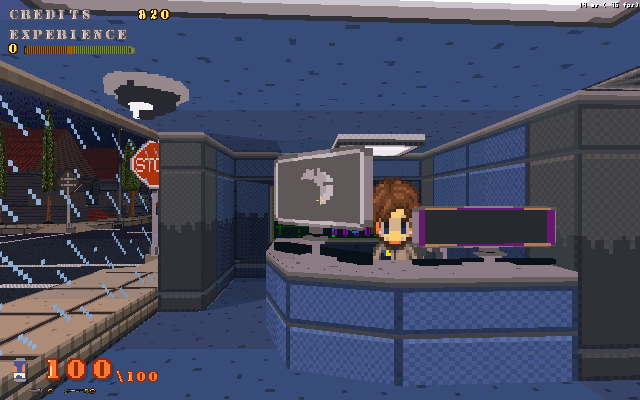
Or a mockup…
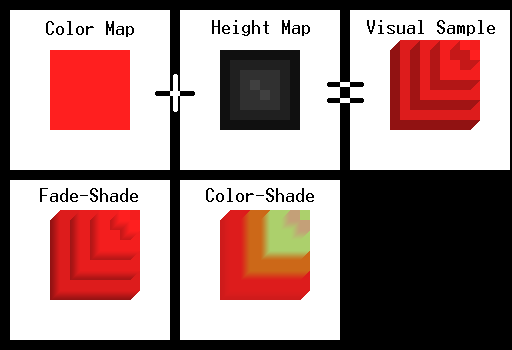
I've been browsing through the old code of The Crawl, the GM 3d version that converted level data into 'smart' models. Smart being that it wouldn't create unviewable walls. Pretty much what I'll be using to create this little side project of a 16 cubed cube dungeon.To create walls and objects, I'll be using something I though up for a voxel simulation project that combined a color map and height map to produce the structure. Nothing terrible original, but makes for creating content much easier.Breaks down as such: First two panels show the color and height maps, combine to create a 3d block based structure. The sides are darkened to create shading.On the next row we have two possible methods of rendering the blocks, one would blend the face color to the side colors to create a smooth shading, this using colored vertexes. Second would blend colors if they were different, less usage of shading and more of color blending.There are some drawbacks to this however, with a shading method I would have to either store a bunch of shaded versions of possible colors or dynamicly adjust them. However blending between color and color is rather easy, just need to set the vertex to the proper color to create a blend.I also used this method to create the fake shading in The Crawl, 3d version. The U3d version got dumbed down with a lack of vertex coloring and using texture layers instead.Of course this project will need no textures, just reference sprites. I plan on having a simple editing program to convert this into usable data for the engine itself.Sorry no wall of images, just one hand done one.But I do have a few useful tips for those playing with GM's 3d.One I learned from reading on ray-tracing, or ray-casting to be specific.for(a = 0; a < 361; a +=1;){global.cosSTORE[a] = cos(a*pi/180)*100global.sinSTORE[a] = sin(a*pi/180)*100}Using that bit of code on startup to save all your Cos and Sin operations that get handled with the camera. One thing that computers hate, is multiplying. This should provided one less thing the PC needs to handle.d3d_set_projection_ext(camx,camy,camz, camx-global.cosSTORE[camd], camy-global.sinSTORE[camd], camz+zdir,0,0,1,45,4/3,2,global.draw_depth);camd = direction of camera, and must always be
Is this an engine that's already out or something you are making, because 3d that doesn't draw unviewable walls sounds very useful.
I like the first one most.
I've started working on this recently, using some old projects as reference.
You should be able to use those code bits in any gm 3d game. The camview variables create a rectangle that follows the camera view. Objects that fall in this range will draw.Maybe I'll have a toggle to set draw styles.